

How to Precisely Calculate Heat Loss for the Industrial Tank (Vessel)

When I first received an inquiry for EHT design for a tank, I hesitated. Why? EHT design for pipes is straightforward, as it is based on well-defined parameters. However, EHT design for tanks seemed more ambiguous compared to pipe design.
Let me explain how I initially learned to design EHT for a tank.
In the Chromalox design guide, the equation for calculating heat loss for a tank is explained as follows:
Q = Qt × △T × 2(KTm + KTa) × A
Qt can be found in the table below, according to the insulation thickness.
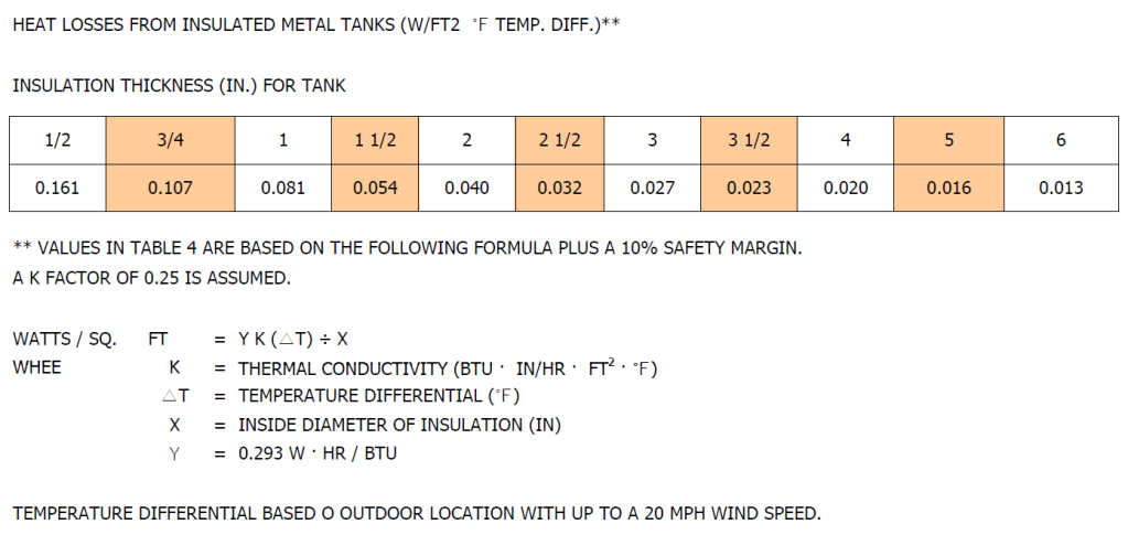
Next, multiply by the temperature difference, ΔT, which is the 'maintain temperature - minimum ambient temperature.'
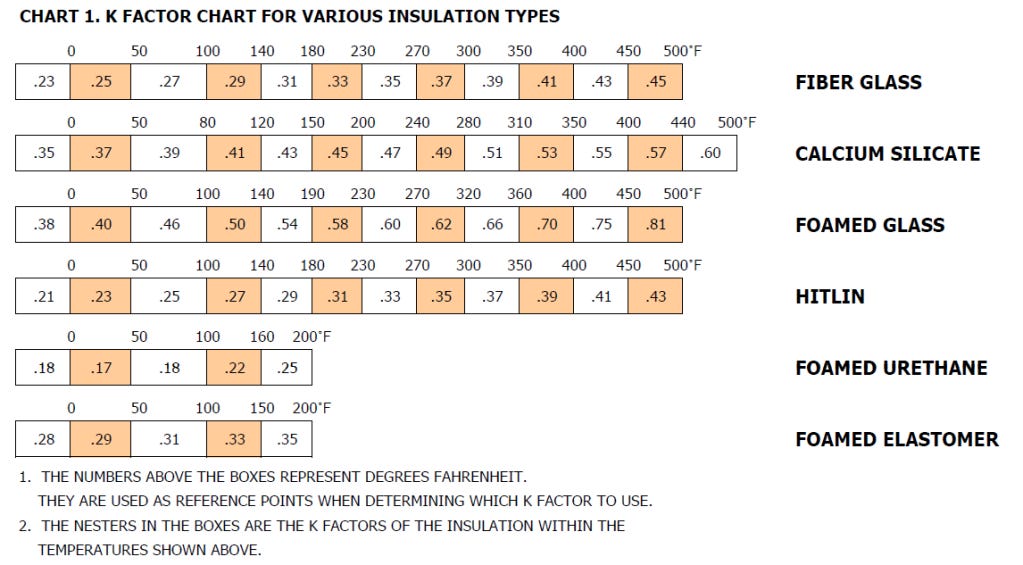
Depending on the maintain temperature and minimum ambient temperature for a specific insulation material, KTm and KTa values are determined from the table below.
Then, multiply by the surface area of the tank, A, to obtain the heat loss, Q.
At this point, we usually apply a safety factor. However, the safety factor applied is often based on the designer’s experience. Sometimes, a 20% safety factor is added, while in other cases, a 100% safety factor is used. Why is there such a large difference? I thought some criteria were needed to determine an appropriate safety factor.
To find the safest method for calculating heat loss for a tank, I decided to check the original equation in the IEEE 515 document.
<Heat Loss Calculation According to IEEE 515>
In the IEEE 515 document, the heat loss calculation for a tank (vessel) is as follows:

1. Heat Loss through Insulation Material (Qins)
Qins is the heat loss through the insulation material.

Qins: Heat loss through insulation (W)
A: Tank surface area of the insulated region (m²)
Tp: Maintain temperature (°C)
Ta: Minimum ambient temperature (°C)
x: Thermal insulation thickness (m)
k: Thermal insulation conductivity at mean temperature (W/m·°C)
hi: Inside air contact coefficient from the tank to the inner insulation surface (W/m²·°C)
hco: Inside air contact coefficient from the outer insulation surface to the weather barrier (W/m²·°C)
ho: Outside air film coefficient from the weather barrier or outer insulation surface to the ambient temperature (W/m²·°C)
The equation accounts for the air between the insulation material and the tank, as well as the air between the outer surface of the insulation and the weather barrier, both of which provide some insulating effect.
For a more conservative calculation, let's assume that only the insulation material provides the insulating effect for the tank. In this case, the heat loss through the insulation material is calculated as follows:
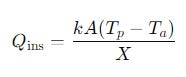
k: Thermal insulation conductivity (W/m·°C)
A: Tank surface area of the insulated region (m²)
x: Thermal insulation thickness (m)
The equation in the Chromalox Design Guide is derived from this equation. This means the calculated Q value from the Chromalox Design guide assumes the entire tank is 100% fully covered with insulation, without any gaps that would cause heat loss.
But what if the tank is sitting on a concrete surface, and the bottom of the tank is not insulated?
2. Slab Surface Area
If the tank is on a concrete slab, we must consider the bottom part separately from the insulated areas. Usually, the edge of the slab experiences more heat loss, while the center has less. Once the temperature of each node is known, the following equation can be used to calculate the heat loss for that region of the slab.
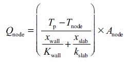
To calculate the exact additional heat loss through the slab surface, we need to calculate Qnode for each node and sum them up. This can be done using engineering software.
Approximately, you could expect a 20% safety margin when the tank is on a concrete slab.
3. Support heat loss
Supports in contact with the tank wall introduce additional heat loss, which can be calculated as follows:

Qsupt: Heat loss for individual support (W)
Ac: Cross-sectional area of the support section that protrudes through the insulation (m²)
P: Perimeter of the support section (m)
Tp: Maintain temperature (°C)
Ta: Minimum ambient temperature (°C)
ks: Thermal conductivity of the support (W/m·°C)
hf: Convection coefficient from the exposed support surface to the ambient air (W/m²·°C)
ε: Efficiency of the fin, which is user-defined. In most cases, it is set to 1.
The heat loss through the supports depends on factors like the support material, cross-sectional area, and the number of support
Based on these factors, an additional 10–20% safety factor due to the supports can be estimated.
4. Manhole heat loss
If manholes are in contact with the fluid, their heat loss can be calculated using the same equation for insulation material heat loss.
If the manholes are fully insulated, the heat loss will be minimal, and can often be neglected.
However, if part of the tank is uninsulated (e.g., a glass window or a top coverless bag filter), the heat loss will be significantly higher.
Depending on various factors, the heat loss from uninsulated areas can be up to 10 times greater than from insulated ones. In such cases, consider the area size and multiply the heat loss through insulation by 10 to estimate the additional heat required.
<Conclusion>
The heat loss of a tank (vessel) depends on multiple factors.
Basically, 20% safety margin is encouraged.
If there is a concrete slab, an additional 20% is suggested. For supports, an extra 10–20% is recommended.
If there are uninsulated parts on the tank, additional heat loss should be accounted for, approximately 10 times the ratio of the uninsulated area to the total surface area of the tank.
These values are not exact but are estimations.
Designers should understand the factors that impact heat loss and apply appropriate safety factors to ensure an accurate and safe design.